Assembled Design
The probe has been shortened for the purpose of the picture. The image is not drawn to scale.

Connector- Electrical Feed Through and KF-16 vacuum fitting
Two 19-pins electrical feedthroughs were are attached to cube cover that was then placed onto the aluminum connector shown in Figure 1. The two feedthroughs were placed on either side of the connector. The KF-16 vacuum fitting must be placed on the top side of the connector to allow the vacuum pump to be easily connected to the KF-16 vacuum fitting.


The 0.069 inch radius is a tapered hole used for a Philips No. 6 (⅜) screw. The 0.492 inch and 0.434 inch radii are the inner and outer diameters of a groove utilized for an Ultra-compressible O-ring. While the 0.365 inch radius is a hole through all the sides of the connector (total of 6 holes).
Wiring inside Stainless Steel Rod
The 49 inches long thin-walled stainless steel rod (5/8 inch diameter), shown in Figure 2.,will house manganin wires, which are used to supply a current and measure the voltage difference. Manganin wires are 86% copper, 12% manganese, and 2% nickel; they are used for their poor thermal conductivity, which will allow reduction in room-temperature leak. The wires are insulated so that shorted wires/circuit and electrical discharges are avoided.

Figure 2. Stainless steel rod Dimensions
Stage Design
The probe to be produced consists of an aluminum connector from the top end of the thin walled stainless steel rod. At the other end, a copper stage is connected to the rod using an interference fit, or a press fit. Interference fit is a fastening between two parts, which is achieved by friction after the parts are pushed together, rather than any other fastening method. However, this is not enough to secure the inner vacuum environment. Therefore, the team also resorted to silver soldering to fill in air gaps between the stainless-steel rod and copper stage after attachment.
The chip carrier placed in the chip socket must be in direct contact with the stage to allow thermal conduction. The stage is thus designed as shown in Figure 3A. The higher compartments is compatible with the shape of the socket, which allows direct contact between the chip carrier and the stage after attachment.

The chip carrier placed in the chip socket must be in direct contact with the stage to allow thermal conduction. The stage is thus designed as shown in Figure 3A. The higher compartments is compatible with the shape of the socket, which allows direct contact between the chip carrier and the stage after attachment.

Figure 3A. Stage design - Front View
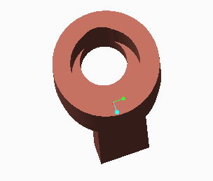
Figure 3B. Stage design - Back View

Figure 3C. Stage design - Dimensions
Radiation Shield Design
The radiation shield's , shown in Figure 4, end matches that of the cylindrical part of the copper stage so that it would be self-locking. The air gaps that might be present will be avoided by using wood's alloy between the shield and the angled side of the stage.
 Figure 4A. Radiation Shield 3-D Design

Figure 4B. Radiation Shield Design Mechanical Drawing


Figure 4B. Radiation Shield Design Mechanical Drawing
No comments:
Post a Comment