Project Overview

Figure 1. Original Dipping-probe observed at "X" university
To quickly cool a sample to a very low temperature, you can submerge it in a cryo-liquid, which is contained in a Dewar. For the purpose of this experiment, Liquid Helium is used to lower the temperature of the sample. Liquid Helium is used for its remarkable properties. First, it has very low boiling points and critical temperatures. In addition, 3-He and 4-He do not become solid under their own vapour pressure even when cooled down to absolute zero. [1]
To characterize and measure the voltage difference of a sample at low temperatures, a cryogenic probe can be utilized. The probe shown in Figure 1 consists of an electrical feed-through (connector) from one end that supplies a current; the current flows through copper wires, which are used for their high electrical conductivity, that are protected by a thin stainless steel rod. Stainless steel is used for its low electrical and thermal conductivity. A copper stage is sealed to the stainless steel rod by a brass ring. The observed probe’s stage had a connector with 6 copper pins, 4 pins can be utilized to measure one sample, and a thermocouple, which is used to measure temperature, like shown in Figure 2 .

Figure 2. Sample Stage with a connector and thermocouple
Deliverables
The model probe had several issues that need to be addressed, which are mentioned below. The list also includes an improved environment that will secure a better experiment for the laboratory.
1) Ability to load several samples per measurement
The model probe was able to load only one sample during a measurement session. One sample required four connecting ports and wires. In order to have more, the connector needs to be changed. To enable the researchers to have several samples per measurement, the team decided to use a Dual in-line chip socket compatible with the chip carrier. The chip carrier has 14-connector ports, which can carry up to three samples (4 pins per sample). The wires coming from the stainless steel rod were connected to the chip socket’ leads. The number of wires connected to the lead is proportional to the number of samples that are going to be experimented per measurements. Several complementary chip carriers may be used to load samples in a more time efficient manner.
The model probe was able to load only one sample during a measurement session. One sample required four connecting ports and wires. In order to have more, the connector needs to be changed. To enable the researchers to have several samples per measurement, the team decided to use a Dual in-line chip socket compatible with the chip carrier. The chip carrier has 14-connector ports, which can carry up to three samples (4 pins per sample). The wires coming from the stainless steel rod were connected to the chip socket’ leads. The number of wires connected to the lead is proportional to the number of samples that are going to be experimented per measurements. Several complementary chip carriers may be used to load samples in a more time efficient manner.
2) Stabilizing Temperature
During the experiment, the probe is being dipped in liquid helium, which causes the probe’s temperature, along with the sample, to decrease rather quickly with no control over how fast or when to stabilize it at a certain temperature for a given time interval. The new design aimed to tackle this problem by creating thermal equilibrium around the samples. The state can be maintained by adding a heater to the sample stage. The heater can be controlled and be set to a certain temperature. As the temperature decreases, the wire-heater will receive a current that raises its temperature. The method used will help stabilize the temperature at a certain point for a given time period, which will enable researchers to better study the behaviors of the samples. The heater had to be placed close enough to the sample (0.2 mm away) and be directly in contact with the copper stage to allow thermal induction.
During the experiment, the probe is being dipped in liquid helium, which causes the probe’s temperature, along with the sample, to decrease rather quickly with no control over how fast or when to stabilize it at a certain temperature for a given time interval. The new design aimed to tackle this problem by creating thermal equilibrium around the samples. The state can be maintained by adding a heater to the sample stage. The heater can be controlled and be set to a certain temperature. As the temperature decreases, the wire-heater will receive a current that raises its temperature. The method used will help stabilize the temperature at a certain point for a given time period, which will enable researchers to better study the behaviors of the samples. The heater had to be placed close enough to the sample (0.2 mm away) and be directly in contact with the copper stage to allow thermal induction.
.
3) Semi-vacuum Environment
Due to the usage of a heater, a vacuum is needed to be created around the sample to prevent Liquid Helium evaporation at a faster rate. Although the method caused the probe to cool down slower, it provided better protection and test results.
The connector shown in Figure 4 had a hole to allow the placement of a KF-16 vacuum fitting/flange. The KF-16 had a tube that will have a vacuum pump attached to it. The inner environment of the probe had to be vacuumized and therefore, extra caution had to be taken while designing the probe to allow perfect sealing.
The copper stage was attached to a (⅝ of an inch in diameter) stainless-steel probe using silver soldering, or a press fit. The stage is then covered by a demount-able radiation shield (0.984 inches in diameter). The radiation shield was designed based on the cone seal method for dipping probes shown in Figure 3. To make sure that there are no air gaps between the cylindrical part of the stage and the radiation shield, wood's alloy will be placed in between.
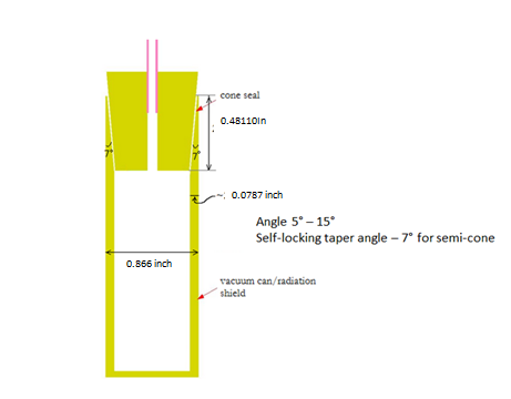
Figure 3. Cone Vacuum Seal dimensions
No comments:
Post a Comment